


")


Introduction
Several years ago, I designed and built a multichannel pre-amplifier based on BurrBrown's PGA2311 volume control chip. It is still playing nicely in my living room, but since then technology has improved (e.g. OLED displays have become common and better ICs are available). Also it lacks some features (like multiple 5.1 inputs, automatic switch off, audio/video playback, smartphone control, etc), so I decided to do a redesign.
Features
This is a modular preamplifier, so the features depend a lot on the different pcb's that are used. The heart of the preamp is the PreampController pcb, which connects the other pcb's, display, buttons, encoder, infrared, etc. Other sensible configurations are:
- Standalone stereo or 5.1 input selection (switch inputs using buttons and infrared, no volume control)
- Standalone DAC in software mode (volume is controlled by the DAC)
- Standalone VolumeControl (without input selection, so single input)
- Combinations of the above (e.g. 5.1 input selection + volume control)
- Stereo input selection + volume control
- Stereo + 5.1 input selection + volume control
- Stereo input selection + DAC + volume control
- Stereo +5.1 input selection + DAC + volume control
- DAC + volume control
An overview of features is given per pcb:
- PreampController
- Convenient user interface
- Infrared remote control
- Control buttons (power/standby, menu, left, right, select)
- Power/standby LEDs
- Display (LCD, OLED, VFD supported)
- Rotary encoder for changing volume
- Power saving features
- Switch power supply of other equipment (e.g. power amplifiers)
- Signal detection to allow automatic switch off after 15 minutes without signal
- UART connector for firmware update and software interaction
- Connect a Raspberry Pi or USB-Serial converter
- Convenient user interface
- StereoInputSelection with 6x analog stereo inputs
- 5.1InputSelectionwith 2x analog 5.1-channel inputs
- DAC with 2x optical and 2x coaxial S/PDIF inputs
- VolumeControl (5.1-channel and chainable 8-channel version)
- Based on CirrusLogic CS3318 volume control chip offering
- Large volume range (-96dB to +22dB in 0.25dB steps)
- Low distortion (-112dB THD+N)
- High dynamic range (127dB)
- Low channel-to-channel crosstalk (120dB)
- Zero-crossing detection for noise-free level transition
- Inputs buffered using OPA2134
- 5.1 channel version
- 1x 5.1 channel volume controlled output
- Integrated Headphone Amplifier
- Hafler circuit for generating virtual surround output from stereo sources
- Loopback connector for future extensions (tone control)
- 8-channel version
- Based on CirrusLogic CS3318 volume control chip offering
- OutputBuffers
- 2x monitor outputs (stereo)
- 3x channel outputs (stereo)
- connectors for balanced outputs
Design
The architecture and the signal flow of a full 5.1-channel preamp are shown in the figure below.
PCBs
The preamp needs a digital single 5V supply and analog dual 9V supply. The functionality of the different pcb's will be described in detail next.
StereoInputSelection pcb


On this pcb, a maximum of 6 cinch inputs can be mounted, using these cinch connectors the pcb can be mounted directly to the back panel of the preamp. The MCP23S08 8-bit SPI I/O extender IC is used to select the desired input using SPI. It switches miniature relays to choose between the inputs. Optionally, 1 input comes from the DAC pcb. Optionally, a 5.1 Input Selection pcb can be stacked on top of this pcb using spacers.
PreampController pcb

The heart of the PreampController is the PIC18F4620 microprocessor. This control board has many connectors:
- 8-bit parallel display, supported displays:
- LCD with contrast input potmeter, backlight supported
- OLED/VFD with or without enable input
- Display needs to be HD44780-compatible (most parallel displays are)
- Preferred is 2x20 character display, 2x16 is supported (main screen shows ok, some menus do not fit)
- Power connector for the power/standby button and power/standby LEDs
- Input selection pcb
- Volume control pcb
- Control buttons (normally-open buttons that can pull the input to GND should be ok)
- Rotary encoder (A/B pulse)
- Infrared receiver (i.e. TSOP1138)
- UART to communicate with Raspberry PI board or connect an USB-serial converter.
An onboard relay can be used to switch the power of external equipment when the preamp is switched on.
CS3318VolumeControl pcb
 mounted")
The Cirrus Logic CS3318 chip is a 8-channel volume control IC, which will be controlled using SPI. The CS3318 needs dual 8 or 9V analog supply, which gives some extra headroom compared to my previous dual 5V preamp. The digital supply and logic is 3.3V, so a voltage regulator and SPI level converters are used to interface the CS3318 with the 5V used in the PreampController pcb.
Currently, 2 versions of this PCB are designed:
- 5.1 channel version with integrated headphones amplifier
- 8 channel version, which can be chained to control additional channels
5.1 channel version
The 5.1 version of this pcb contains an integrated headphone amplifier. For it, 2 channels of the CS3318 are used, the other 6 channels are used to control the 5.1 outputs. The inputs are buffered using OPA2134 opamps. An onboard Hafler circuit is used to create virtual surround for the surround/center/bass channels from the stereo channels. The difference of the stereo channels is used for the surround channels, the sum of the front channels for the center/bass channels. Using a digital output from the PreampController a relay is switched to select whether to use the Hafler virtual surround or the surround/center/bass inputs directly.
8 channel version
The 8 channel version of this pcb contains OPA2134 opamps to buffer the inputs. Additional pcb's can be chained to control additional channels (16-channels currently supported by the software)
Digital Supply pcb
Provides regulated 5V supply for the digital electronics. An example of a combined supply pcb for both digital and analog supply is the TripleRegulated_EI38_supply. A suitable separate supply is the DualRegulated_15/25VA_supply.
Analog Supply pcb
Provides regulated 9V supply for the analog electronics on the CS3318VolumeControl pcb, optionally also for the DAC pcb. An example of a combined supply pcb for both digital and analog supply is the TripleRegulated_EI38_supply. A suitable separate supply is the DualRegulated_15/25VA_supply.
5.1InputSelection pcb


A separate pcb with 2x 5.1 inputs can be stacked on top of the StereoInputSelection pcb. Using 2 outputs of the MCP23S08 8-bit I/O extender on the StereoInputSelection these inputs can be selected.
CS4398DAC pcb
This DAC is based on CS8416 receiver chip and CS4398 DAC chip and is described in detail on its own project page. It will interface to the PreampController pcb using SPI.
OutputBuffers pcb


The outputs of the CS3318VolumeController pcb can be buffered with this pcb if needed. Also it has connectors for balanced outputs. Cinch connectors can be directly mounted on this pcb, with these it can be mounted easily to the rear panel of the preamp. Analog power for the output buffers is received from the CS3318VolumeControl pcb.
Software
Because I am familiar with C/C++ programming, I decided to use the SDCC (small device c-compiler). It is a free and unrestricted C-compiler for PIC (and other) micro controllers and I already used it in a couple of other projects.
To make future software updates much easier, I added a bootloader, which allows software updates without a dedicated programmer using the UART connector. I tested the software update process in combination with a Raspberry Pi, but it should be possible also with a USB to Serial adapter. The software update needs:
- Unmodified Tiny PIC Bootloader firmware made by Claudiu Chiculita running on the PreampController
- Modified version of Unix Tiny PIC Bootloader Loader software to flash a new hex file in the microcontroller from the Raspberry Pi using the command line.
Note that the Unix Tiny PIC Bootloader Loader software was chosen because it runs from the Raspberry Pi command line and does not need a Graphical User Interface and therefore the software can be updated by logging in remotely. Unfortunately it did not work correctly out-of-the-box and quite some time was needed to modify the program for it to become useful. But finally I managed to get it running properly and it seems to work very reliable and it is fast (software update takes about 30s using baudrate of 115K2). Since an unmodified version of the Tiny Bootloader firmware was used it is also possible to use the Windows flash program that comes with the Tiny Bootloader in combination with a USB-to-serial adapter.
More information about the UART terminal and how to connect a Raspberry Pi can be found on the PreampV2 software page.
Currently the following software functionality is working:
- Buttons
- Display
- Encoder
- Infrared control (RC5/RC5x)
- Input selection
- Volume control (5.1, 1x8 channel and 2x8 channel version of the pcb supported)
- DAC (select inputs, read bitrate/frequency, control volume)
- Menus (input/channel offsets, input names, settings, information, infrared)
- Support different HW setups
- Standalone stereo or 5.1 input selection (switch inputs using buttons and infrared, no volume control)
- Standalone DAC in software mode (volume is controlled by the DAC)
- Standalone VolumeControl (without input selection, so single input)
- Combinations of the above (e.g. 5.1 input selection + volume control)
- Load/Store settings from/to EEPROM
- Detect headphone connection (and mute other channels)
- Detect and visualise signal level
- Generic use of parameters (name, type, value, etc)
- Auto switch off after 30minutes without signal
- Serial terminal communication (e.g. from Raspberry PI)
- Verify HW setup
- Event Handler mechanism (i.e. button press, or infrared control, or terminal function trigger same event, which is handled by same event handler)
TODO:
- Additional IR protocols (RC6, more?)
Measurements
Then the next question are: is it any good, how good is it, can you get me some proof? So, time to put it on the measurement bench. For the measurements I use RMAA with my EMU1212M sound card, which allows to measure extremely low distortion and noise levels. The preamp allows the signals in the chain to be taken out at various stages, so the particular contribution of the Input Selection relays or Output Buffer pcb can be seen as well. I measured the chain at 4 points:
- Right after the DAC pcb to get the best reference measurement
- Monitor Ouputs on the Output Buffer pcb, so including input selection and output buffers
- Front Outputs on the Output Buffer pcb, so including input selection, volume control and output buffers (volume set at 0.0dB)
- Headphones Outputs on the volume control pcb (volume set at -10.0dB)
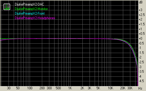
Measurements where done in the chain: sound card optical out -> Preamp -> sound card analog in. All measurements done at 24-bit, 96 kHz. Front measurements done with volume set at 0dB.
Summary
| Test | DjukePreampV2-DAC | DjukePreampV2-Monitor | DjukePreampV2-Front | DjukePreampV2-Headphones |
| Frequency response (from 40 Hz to 15 kHz), dB: | +0.01, -0.12 | +0.01, -0.12 | +0.01, -0.16 | -0.02, -0.18 |
| Noise level, dB (A): | -103.2 | -99.3 | -99.3 | -99.0 |
| Dynamic range, dB (A): | 103.2 | 99.2 | 99.2 | 98.9 |
| THD, %: | 0.0003 | 0.0005 | 0.0008 | 0.0009 |
| IMD + Noise, %: | 0.0020 | 0.0032 | 0.0035 | 0.0036 |
| Stereo crosstalk, dB: | -102.0 | -98.3 | -98.0 | -99.3 |
Complete measurement report can be found here.
Frequency response
Total harmonic distortion
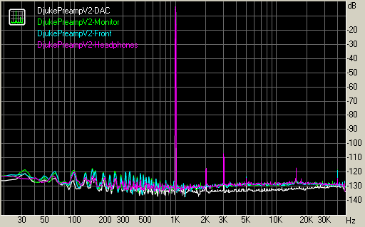
Measurement conclusions
- DAC reference measurements show very low THD and noise levels, limited by the Analog Inputs of the sound card
- Input Selection relays and Output Buffers only degrade the signal marginally
- Volume Control gives a slight increase in THD (0.0003% -> 0.0008%), but values are still very low
User gallery
Djuke
My fully equipped prototype with CS4398DAC, StereoInputSelection, 5.1InputSelection, CS3318VolumeControl, PreampController and a Raspberry Pi2 with HifiBerry Digi+ and Volumio mediaplayer.


Peter Bellamy
Fully featured 5.1 channel amplifier built inside a custom enclosure. Also includes a third party phono preamplifier.


Peter P.
Full 5.1 preamplifier with CS4398 DAC and Raspberry Pi media player built inside a custom cabinet.


